Get the Delrin® design advantage
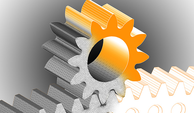
Get solutions to even the toughest gear challenges by turning to Delrin® experts for Finite Element Analysis (FEA).
The Delrin® design team is ready to partner with you to design the optimum gear. From manual calculation to advanced FEA, we know how to accurately predict Delrin® material behavior to help you design better plastic gears.
Gear Design Software
For simulation work, Delrin® uses commercial gear design software which is widely used in the industry to support design of plastic gears and incorporates the most relevant VDI (2736) standards into the software calculation.
For plastic gears, it can predict:
- Failure modes
- Wear calculation
- Contact analysis
- Operating backlash calculation
A number of Delrin® grades have been characterized specifically for this type of gear design software to include general material data, root fatigue, and wear factors.
The software is best used as a screening tool to minimize actual material tests to be run.
Finite Element Analysis (FEA) Techniques Applied to Gears
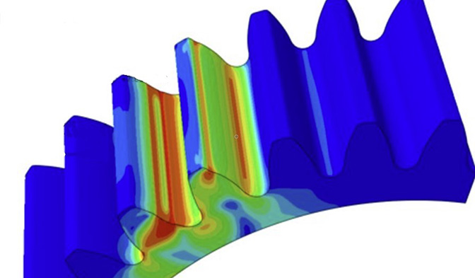
The Delrin® advanced Computer-Aided Engineering (CAE) team provides world-class capabilities to assist customers in their product development.
One such example is FEA design for plastic gears, which offers a realistic simulation of plastic gears’ lifetime, durability, and load sharing.
It is capable of capturing progressive damage, plasticity, and cyclic deformation mechanisms and will provide valuable insight during the design process.
In this example in Figure 1, a 40-tooth, 0.8 module gear set was modelled, with the drive gear and driven gear being identical.
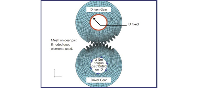
In actual gear fatigue life testing, the gears ran at 100 rpm at a torque of 3 N•m, with failure usually occurring in about 10 minutes. The same gears were modeled by Delrin® engineers using a finite element program as shown. The driven gear was fixed on its ID, while the driver had 3 N•m torque uniformly distributed on its ID. The material for this test was Delrin® 100P.
In a non-linear finite element analysis, the load is applied in increments until the maximum load is achieved. Figure 2 shows some of the increments. In each succeeding increment, the Von Mises stresses are higher and spread out to more teeth as these teeth come in contact.
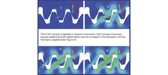
Figure 3 shows the Von Mises stresses in the test gears at maximum load, 3 N•m. This figure shows that three sets of teeth are in contact simultaneously at the maximum torque, thus a certain amount of load sharing occurs. However, the yield stress is exceeded in a few locations.
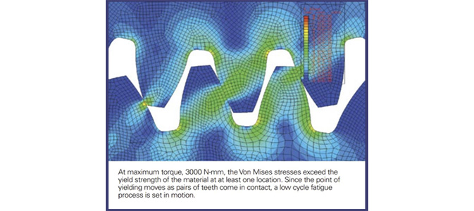
In this case, when repeated stresses are in excess of the yield stress, low cycle fatigue occurs. Meaning failure takes place after a relatively few cycles. This example shows that the software accurately predicts the failure mode at relatively low cycle numbers, as validated in the testing.
Every case is different, but by running such simulations, Delrin® engineers can help highlight potential issues and assist you in optimizing gear designs for extended service lifetimes.

